SCR : Construction, Working and V-I characterstics - Detailed
Written On Friday, October 18th, 2013 At 08:35:27 am By Sunil Saharan
4152 Times
In this article we will discuss construction and working of SCR in detail with V-I characteristics
We have already discussed basic construction, symbol and working of thyristor in Construction of SCR(Thyristor) | SCR Internal Arrangement
 An SCR works in three modes. These modes are
Forward blocking mode
Forward Conduction mode
Reverse blocking mode
These modes are explained below
An SCR works in three modes. These modes are
Forward blocking mode
Forward Conduction mode
Reverse blocking mode
These modes are explained below
 Break over Voltage:
When the gate of the Silicon Controlled Rectifier is open, then the minimum amount of forward voltage which is required for Silicon Controlled Rectifier to start conducting heavily is known as Break over Voltage.
Peak Reverse Voltage:
When Cathode Terminal of SCR is kept positive with respect to anode, then the maximum reverse voltage at which Silicon Controlled Rectifier remains in OFF state or doesn't conduct , is called Peak Reverse Voltage.
Holding Current:
When the gate terminal of SCR is kept open, then the maximum value of anode current at which Silicon Controlled Rectifier is turned OFF from conducting condition, is known as Holding Current.
Forward Current Rating:
The maximum value that an Silicon Controlled Rectifier(SCR) can bear or handle without burning is called Forward Current Rating.
Break over Voltage:
When the gate of the Silicon Controlled Rectifier is open, then the minimum amount of forward voltage which is required for Silicon Controlled Rectifier to start conducting heavily is known as Break over Voltage.
Peak Reverse Voltage:
When Cathode Terminal of SCR is kept positive with respect to anode, then the maximum reverse voltage at which Silicon Controlled Rectifier remains in OFF state or doesn't conduct , is called Peak Reverse Voltage.
Holding Current:
When the gate terminal of SCR is kept open, then the maximum value of anode current at which Silicon Controlled Rectifier is turned OFF from conducting condition, is known as Holding Current.
Forward Current Rating:
The maximum value that an Silicon Controlled Rectifier(SCR) can bear or handle without burning is called Forward Current Rating.
SCR : Construction and Symbol
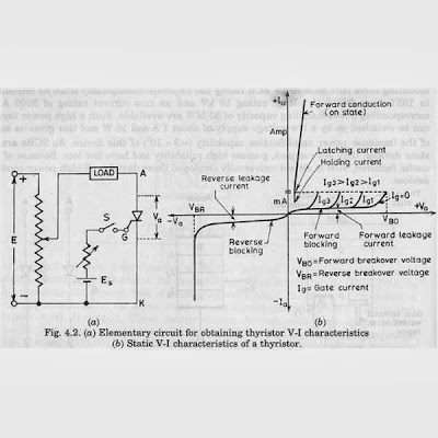
SCR (Silicon Controlled Rectifier) is a four-layer (p-n-p-n) unidirectional device with three terminals, namely, anode (A), cathode (K) and gate (G) having three p-n junctions generally named as J1,J2,J3. The symbol and construction of SCR is shown below:
Forward blocking mode
In this mode of operation anode is made positive with respect to cathode and gate is kept at zero potential. In this connection arrangement shown above junction J1 and J3 are forward biased while J2 is reversed biased due to which current is blocked and only a small amount of current called leakage current will flows from anode to cathode due to minority charge carriers till applied voltage reaches its break over value at which junction J2 breakdown and at this break over voltage it starts conducting but below break over voltage it offers very high resistance to the flow of current through it and said to be in off state.Forward Conduction mode
In this mode, SCR conducts currents from anode to cathode with a very small voltage drop across it (as the resistance of SCR reduced due to breakdown of J2, hence voltage drop across it decreases instantaneously). A SCR is brought from forward blocking mode to forward conduction mode by turning it on by exceeding the forward break over voltage or by applying a gate pulse between gate and cathode. In this mode, SCR is in on-state and behaves like a closed switch. Voltage drop across SCR in the on state is of the order of 1 to 2 V depending on the rating of SCR. It may be seen from the voltage drop increases slightly with an increase in anode current.Reverse blocking mode
When cathode is made positive with respect to anode with gate open, SCR is reverse biased as shown here. Junctions J1 & J3 are seen to be reverse biased whereas junction J2 is forward biased. The device behaves as if two diodes are connected in series with reverse voltage applied across them. A very small leakage current of the order of a few milliamperes (or a few micro amperes depending upon the SCR rating) flows. This is reverse blocking mode, called the off-state, of the SCR. If the reverse voltage is increased, then at a critical breakdown level, called reverse breakdown voltage VBR, an avalanche occurs at J1 and J3 and the reverse current increases rapidly. A large current associated with VBR gives rise to more losses in the SCR. This may lead to SCR damage as the junction temperature may exceed its permissible temperature rise. It should, therefore, be ensured that maximum working reverse voltage across a SCR does not exceed VBR. When reverse voltage applied across a SCR is less than VBR, the device offers high impedance in the reverse direction. The SCR in the reverse blocking mode may therefore be treated as an open switch. The Complete V-I Curve is shown below: SCR : Working and V-I Characteristics
Tags :SCR Construction, V-I Characteristics of thyristor, breakover voltage, important terms related to SCR
Article Was Last Updated on Monday, March 12th, 2018 At 03:10:53 pm
Follow steps described here at your own risk. Privacy Policy
सत्य के मार्ग पे चलते हुए कोई दो ही गलतियाँ कर सकता है; पूरा रास्ता ना तय करना, और इसकी शुरआत ही ना करना |
There Are Only Two Mistakes One Can Make Along The Road To Truth: Not Going All The Way, And Not Starting.


Site Statistics
Stats at a Glance
Articles: 54
Viewed: 391655 Times
Photos : 53
Viewed: 576139 Times
Questions : 2344
Viewed: 200563 Times
Page Load No. 3168085
Photos
Take Quiz
1 Liners For Exam
Show Questions(1 by 1)
©2011-2023 SunilSaharan.In